Original Link: https://www.anandtech.com/show/4130/the-battle-of-the-p67-boards-asus-vs-gigabyte-at-190
The Battle of the P67 Boards - ASUS vs. Gigabyte at $190
by Ian Cutress on January 20, 2011 4:15 PM EST- Posted in
- Gigabyte
- Motherboards
- Asus
- P67
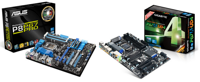
In the world of motherboards and manufacturer competition, the idea is to beat your competitor. To develop the product, with more features, more fancy gadgets, and perform better than your competitor at every price point. Today, we pit arguably the two most popular motherboard vendors at a price point that will see a significant number of sales from consumers and enthusiasts alike – the ASUS P8P67 Pro and the Gigabyte P67A-UD4, which were both released during the Sandy Bridge week for $190. Forget all the marketing fluff; this is a showdown!
When a new platform is released, a myriad of motherboards hit the shelves at the same time. Each vendor will usually come out with a few products, targeting their prospective markets. Big motherboard players, like ASUS and Gigabyte, will release motherboards ranging from the cheap low end, to that high-end halo product. They will bombard you with data, ideas, concepts, and reasons why their high-end products are better than their low end – in terms of numbers, features, or what is in the box. Whether you can really trust what each manufacturer says on the box depends on the interpretations of the benchmarks and analyses by review sites like AnandTech.
At the time of writing, Newegg has 56 Sandy Bridge motherboards available – 22 for H67 and 34 for P67. Of those in the P67 range, you can pick up an Intel motherboard for as little as $115, or an ASUS as expensive as $320. So what makes that expensive motherboard worth almost three times as much as the low-end board? What makes a $200 board better than a $150 board? Features? Warranty? Overclockability? Price? All of these points, while valid, carry different weight with every different consumer.
I reviewed the ASRock P67 Extreme4 at the Sandy Bridge release, and they offered a great product that is available online for $153. Today, we have two boards released at $190 by two of the biggest motherboard manufacturers – the ASUS P8P67 Pro, and the Gigabyte P67A-UD4. Firstly, the question is: if you had $190, which one would you buy? Then secondly, we have to ask: are these boards worth the ~$40 difference to the P67 Extreme4? Luckily, at least in my opinion, after using all three of the boards, the answers to both of these questions were self-evident.
Firstly, let us tackle the ASUS P8P67 Pro.
The ASUS P8P67 Pro fits near the beginning of the line-up in the ASUS launch, which in terms of ATX sized boards include the P8P67, the P8P67 Pro, the P8P67 Evo, the P8P67 Deluxe, the Sabertooth P67, the P8P67 WS SuperComputer and the top end Maximus IV Extreme. Therefore, with that in mind, we would expect to be looking at something above the base – slightly more (or better) features than the cheap boards available, enough to warrant the price difference. An overview of the P8P67 series is below:
| P8P67 Series | ||||||
| P8P67 LE | P8P67 | P8P67 PRO | P8P67 EVO | P8P67 Deluxe | ||
| Price | $140 | $160 | $190 | $210 | $235 | |
|
SATA 6 Gb/s SATA 3 Gb/s eSATA |
3 4 1 |
4 4 1 (bracket) |
4 4 2 |
4 4 2 |
4 4 2 |
|
|
CrossFireX SLI |
Yes No |
Yes No |
Yes Yes |
Yes Yes |
Yes Yes |
|
|
USB 3.0 USB 2.0 |
2 14 |
4 (2 via header) 12 |
||||
| LAN | 1 | 1 | 1 | 2 | 2 | |
| Bluetooth | No | Yes | Yes | Yes | Yes | |
Visual Inspection
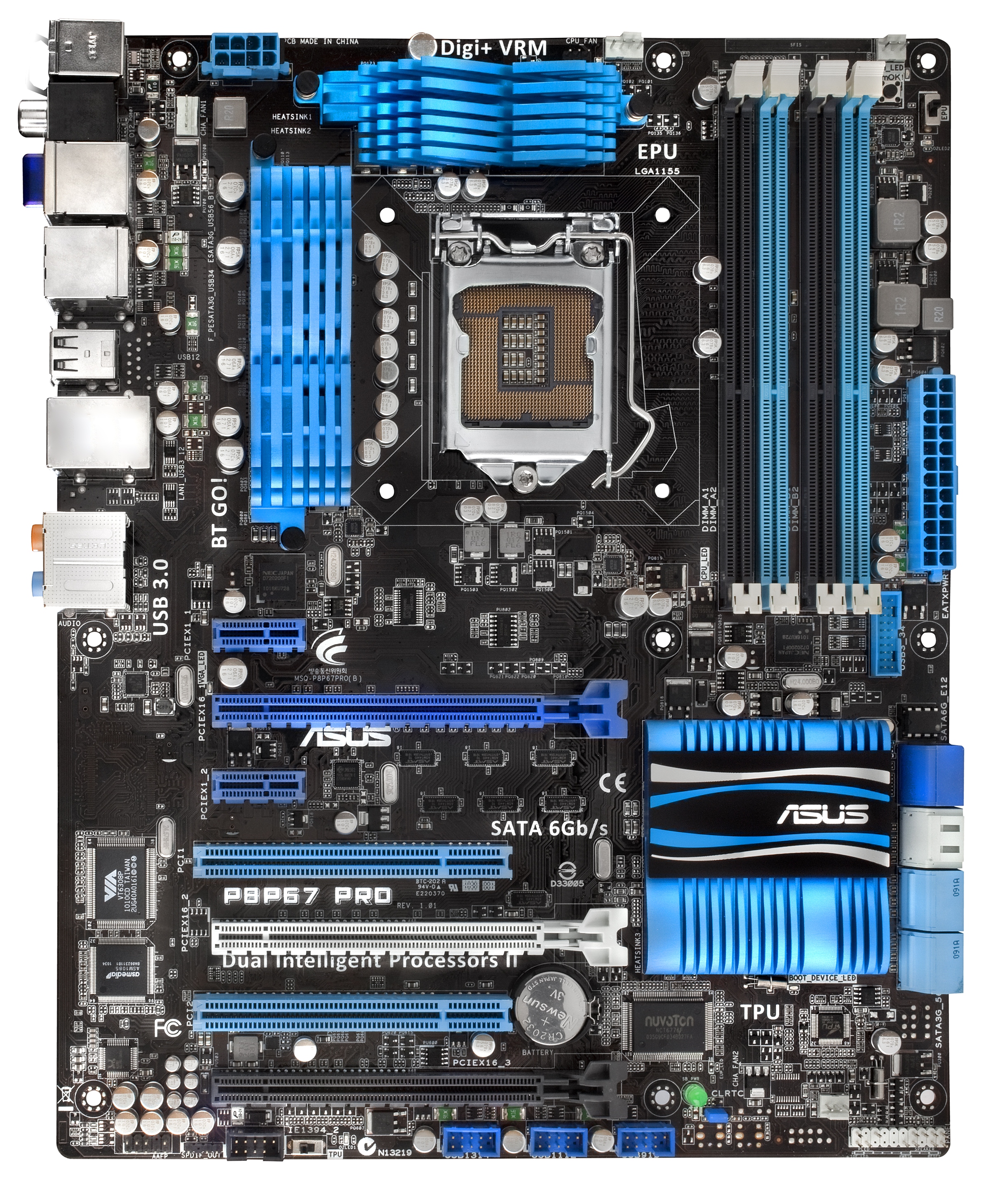
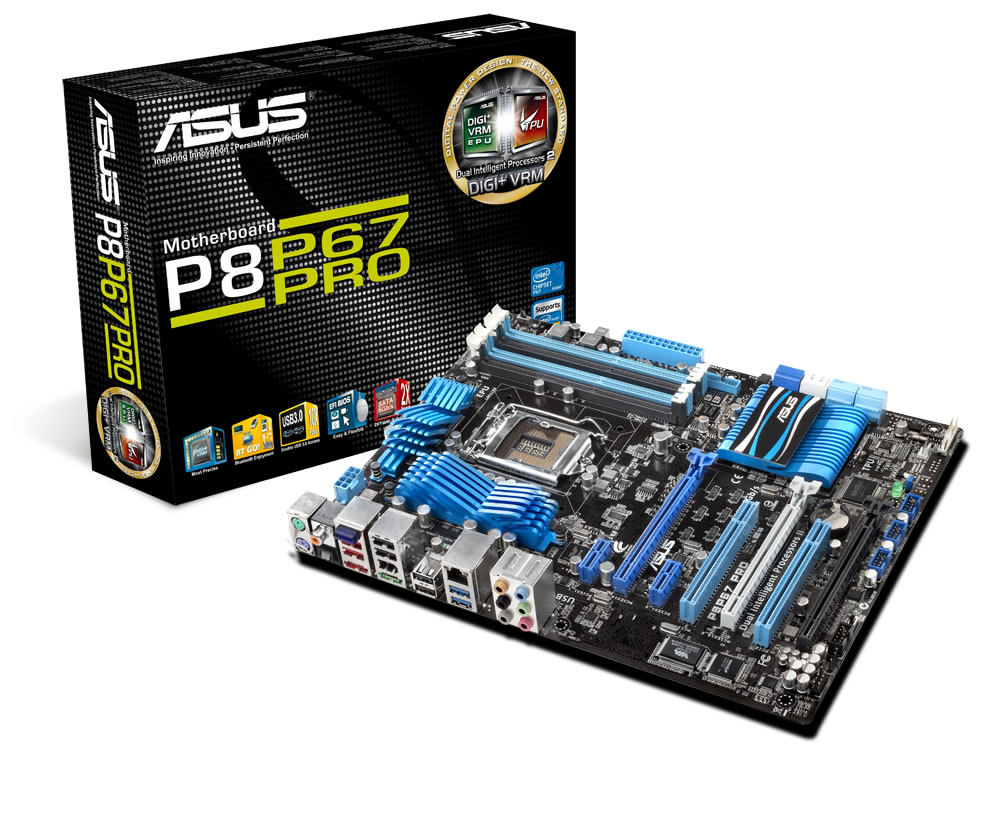
ASUS have gone with the blue/white/black livery for the Pro board, with a 12+2 digital VRM design covered by slanted blue heat sinks. The socket itself is relatively clear, easily allowing large 1155/1156 CPU coolers to be fitted (remember, 1155 mounting holes are the same as 1156). The CPU fan header is located at roughly one o’clock from the socket itself, with a chassis header to the right of the DIMM slots, presumably for HDD bay type fans.
Next to this header are the EPU switch and the MemOK buttons. The EPU switch enables Energy Processing Unit, which is geared towards saving energy – this encompasses power gating certain features that are never used/used rarely, and declocking when less compute is required. The MemOK button is a physical override for overclocked memory – by holding it down until the red light comes on, at next boot, the UEFI will override the memory settings to something more suitable.
The SATA connectors come in blue (SATA 3 Gb/s), white/grey (SATA 6 Gb/s provided by the chipset) and navy blue (SATA 6 Gb/s provided by a Marvell controller). There is a USB 3.0 header also here, near the DIMM slots. These are all next to the ASUS logo and chipset cooler, which underneath have another chassis header and a green power light. This board is lacking both a debug LED and power/reset buttons on the main board, much to our disappointment.
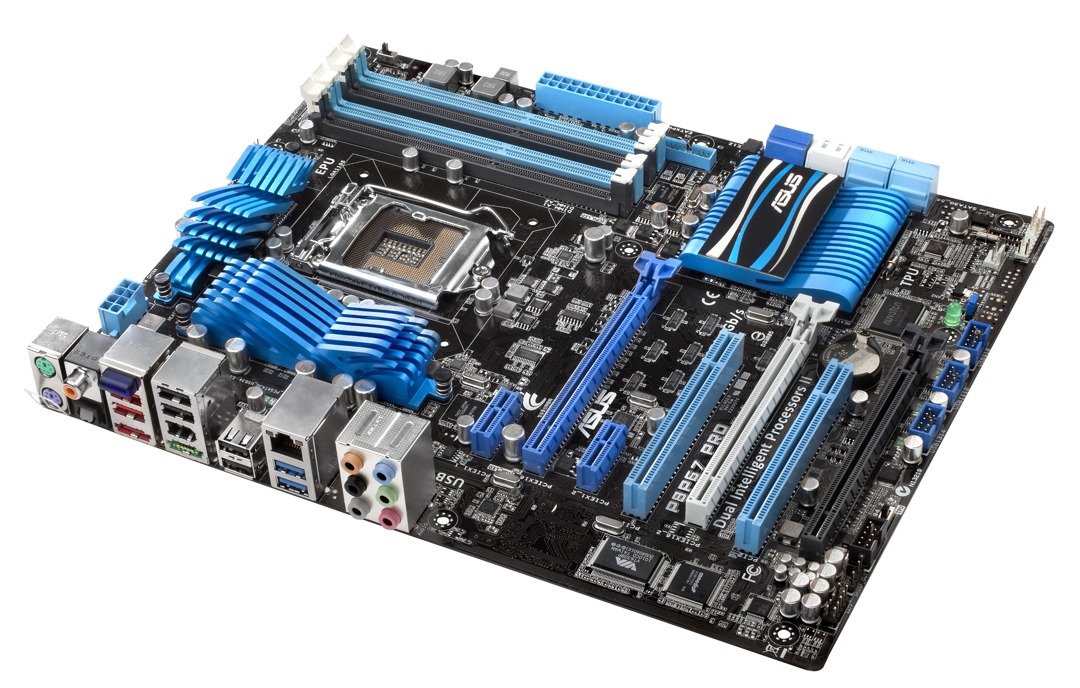
The PCI slots are well laid out, with a PCIe 1x at the top and enough space between the first two PCIe x16 for a PCI card, meaning that at least one is available if all three PCIe x16 are occupied with dual slot cards. The black PCIe x16 slot is wired up as an x4 slot (as it shares bandwidth with the x1 slots, two USB 3.0 ports and the eSATA ports), and with a dual slot card in there, will cover most of the board USB headers.
The TPU switch is underneath the PCI slots, and performs the same function as the TurboV EVO software in the OS to optimise the system for a decent and stable overclock.
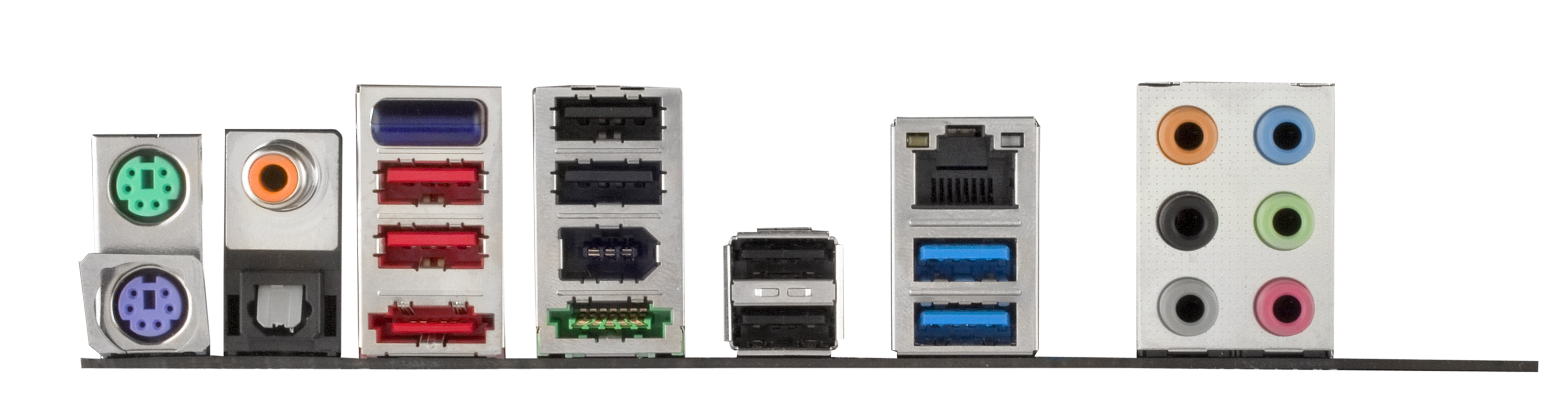
The back panel is standard, with dual PS/2 connectors, SPDIF outputs, USB 2.0 slots, USB 3.0 slots, Firewire, eSATA, audio and Ethernet. The blue module three from the left is the ASUS Bluetooth module, designed to communicate with Bluetooth devices to enhance overclocking or utilise music management. The gigabit Ethernet is handily powered by an Intel chip.
Board Features
| ASUS P8P67 Pro | |
| Market Segment | Performance |
| CPU Interface | LGA 1155 |
| CPU Support | i3/i5/i7 Sandy Bridge |
| Chipset | P67 |
| Base Clock Frequency | 100 MHz, 80 MHz to 300 MHz in 0.1 MHz intervals |
| DDR3 Memory Speed | 1333 MHz by default, 800-2133 MHz supported |
| Core Voltage | Auto, 0.800V to 1.990V in 0.005V intervals |
| CPU Clock Multiplier | Dependant on CPU |
| DRAM Voltage | Auto, 1.20V to 2.20V in 0.00625V intervals |
| DRAM Command Rate | Auto, 1N to 3N |
| Memory Slots |
Four 240-pin DDR3 DIMM slots in dual-channel Regular unbuffered DD3 memory Up to 32GB total supported |
| Expansion Slots |
3 x PCI Express 2.0 x16 slots (PCIe 1 and 2 operate at x16 in single mode or x8/x8 in dual; PCIe 3 operates in x4 mode) 2 x PCI Express 2.0 x1 slots 2 x PCI slots Supports ATI Crossfire Supports NVIDIA SLI |
| Onboard SATA/RAID |
2 x SATA 6.0 Gb/s ports (gray) supporting RAID 0, 1, 5 and 10 4 x SATA 3.0 Gb/s ports (blue) supporting RAID 0, 1, 5 and 10 2 x SATA 6.0 Gb/s ports (navy blue) from Marvell 9120 (No RAID) 2 x eSATA 3.0 Gb/s ports (1 x Power eSATA) from JMicron JMB362 |
| Onboard |
4 x SATA 3 Gb/s w/ RAID 4 x SATA 6 Gb/s (2 w/ RAID) 1 x USB 3.0/2.0 connector supports additional 2 USB ports (19-pin) 3 x USB 2.0/1/1 connectors support additional 6 USB ports 1 x IEEE1394a connector Front panel audio connector 1 x S/PDIF Out Header System Panel(Q-Connector) 1 x MemOK! Button 1 x EPU switch 1 x TPU switch |
| Onboard LAN | Intel® 82579 Gigabit Ethernet |
| Onboard Audio | Realtek® ALC892 8-Channel HD Audio |
| Power Connectors | 24-pin EATX Power connector 8-pin EATX 12V Power connector |
| Fan Headers |
1 x CPU Fan connector (4-pin) 2 x Chassis Fan connectors (1 x 4-pin; 1 x 3-pin) 1 x Power Fan connector (3-pin) |
| I/O Panel |
1 x PS/2 Mouse port (green) 1 x PS/2 Keyboard port (purple) 1 x Coaxial S/PDIF Out port 1 x Optical S/PDIF Out port 1 x Bluetooth module 2 x eSATA ports (1 x Power eSATA) 1 x IEEE1394a port 1 x LAN (RJ45) ports 2 x USB 3.0/2.0 ports (blue) 6 x USB 2.0/1.1 ports 8-channel Audio I/O ports |
| UEFI Revision | 1053 (Release UEFI) |
In the Box
- I/O shield
- USB 3.0 rear bracket
- SLI 2-slot bridge
- 4 x right-angled SATA connectors
The USB 3.0 rear bracket connects in the board to the USB 3.0 header, and stretches across the GPUs and intended for the bracket position between the PCIe slots. The cord is just long enough for this, but this kit will not reach to other bracket positions if you already require that PCI slot between the PCIe slots and both PCIe x16 slots for GPUs.
Software
ASUS Ai Suite II
ASUS have wrapped all their OS features into one overall program, called Ai Suite II. Through this program, you can overclock, auto tune, enable/disable EPU, control the VRMs, control the fans, and update the UEFI. In my experience, it works rather well.
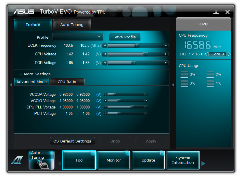
Ai Suite II initially comes up as a toolbar, and selecting one of the buttons creates a popup menu, from which you select the feature you want to use. This is a roundabout way of doing it; I would have preferred a tabbed system personally. The first screen is the TurboV EVO module, the heart of the TPU. On the fly BCLK, voltages, and CPU ratios are applicable here. Increasing various parameters results in them turning yellow, to see that they are all changed, and on clicking apply, all modifications are made. The only downside of this overclocking mode is in the inability to modify the RAM sub-timings on the fly.
The auto-tuning section is a one-button click. The program then restarts the computer, loads into the OS a couple of times, and stability tests the system. I like this feature – the i5-2500K went from 33x multiplier at 100 BCLK to 43x at 103.5 BCLK, giving a total overclock at 4.55 GHz. Every time I used it, it caused at least one blue screen, but as long as I left to its own devices, it provided a suitable overclock. I managed to get a better 24/7 overclock, which I describe in the overclock section, which means the auto-tuning could be considered a little conservative.
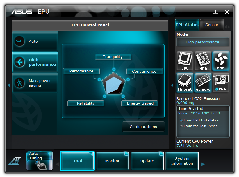
The EPU control panel gives the user greater control over the EPU, in terms of power saving. Alongside the fan controller, the user can adjust the level of power saving in terms of VCore, chipset voltages, HDD spin downs, etc. for when the computer isn’t doing anything too strenuous.
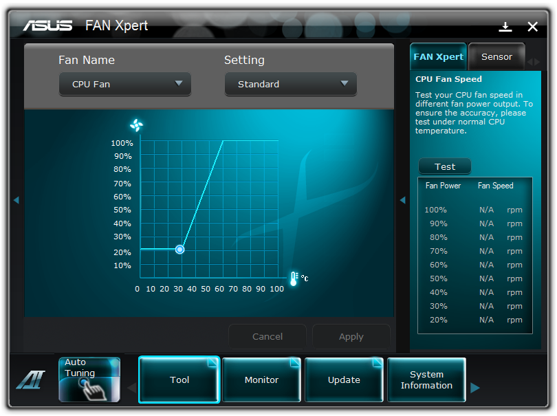
This software also allows complete temperature control of two of the fan headers. As shown below, we can describe the fan power curve against temperature in its entirety, or at preset levels provided by ASUS.
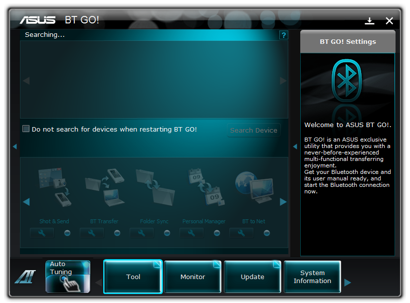
The BT GO! software allows Bluetooth connection with your smartphone (Android, Apple, Windows Mobile, Symbian). If you can download the BT Turbo Remote software from the respective marketplace, you can also overclock via your smartphone – despite being able to connect to BT GO! (and having very little options apart from music control), I was unable to download the BT Turbo Remote software from the Android marketplace. I am currently running a HTC Hero smartphone using a custom ROM to enable Android 2.2 functions. At the time of publication, this program was not available to me on the marketplace.
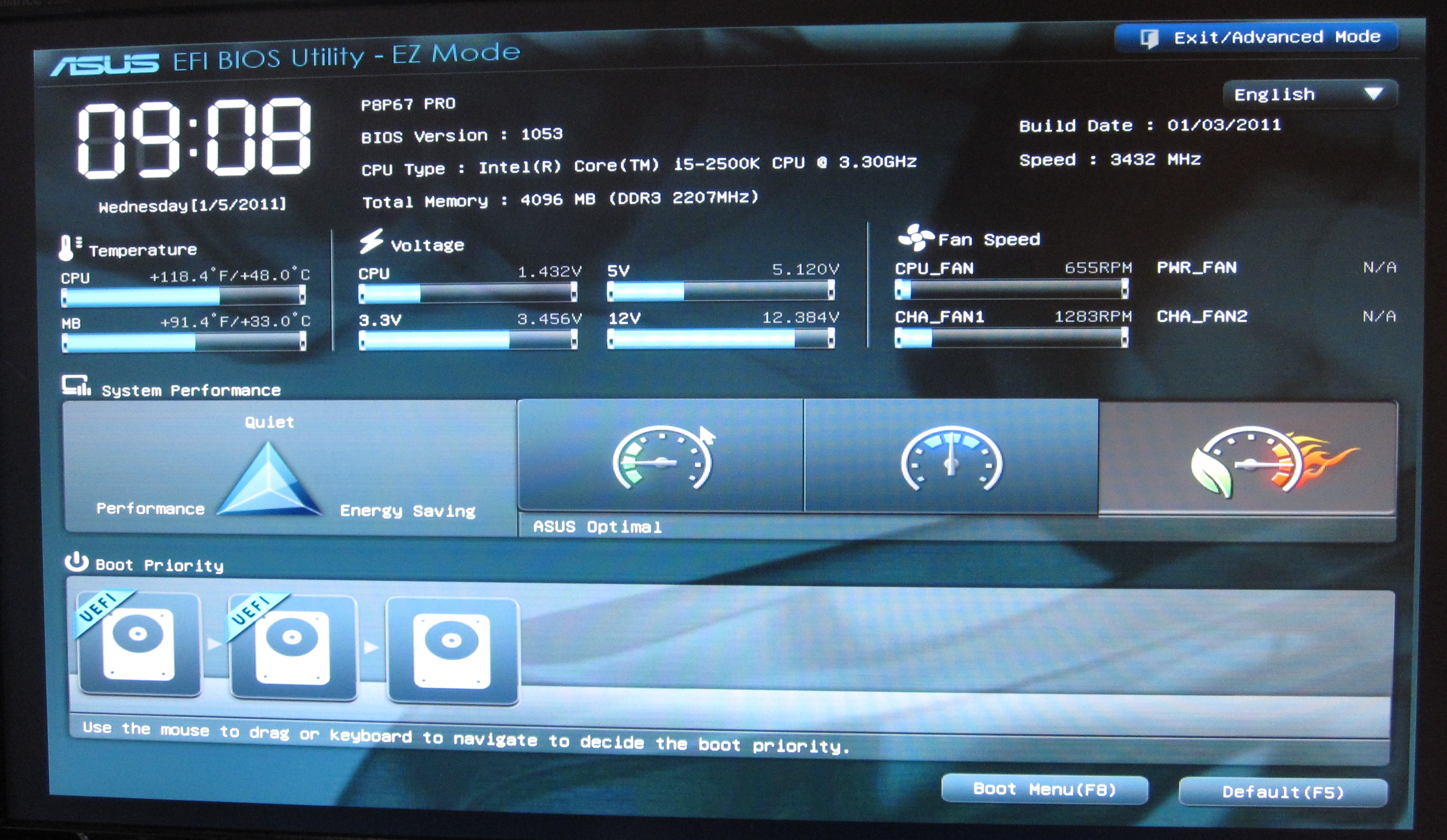
ASUS bring a lot of innovation to the UEFI table over what I have seen from other vendors. The implementation of EZ mode (‘easy’ mode, for us Brits that pronounce that letter ‘zed’) gives the screen below on first entering the UEFI. At a glance, it gives vital motherboard information – CPU, speed, memory, temperatures, voltages, fan speeds, and boot order. The boot order is a great addition, allowing the user to drag-click the order they want. Also available is the three performance options – low power, standard, and performance.
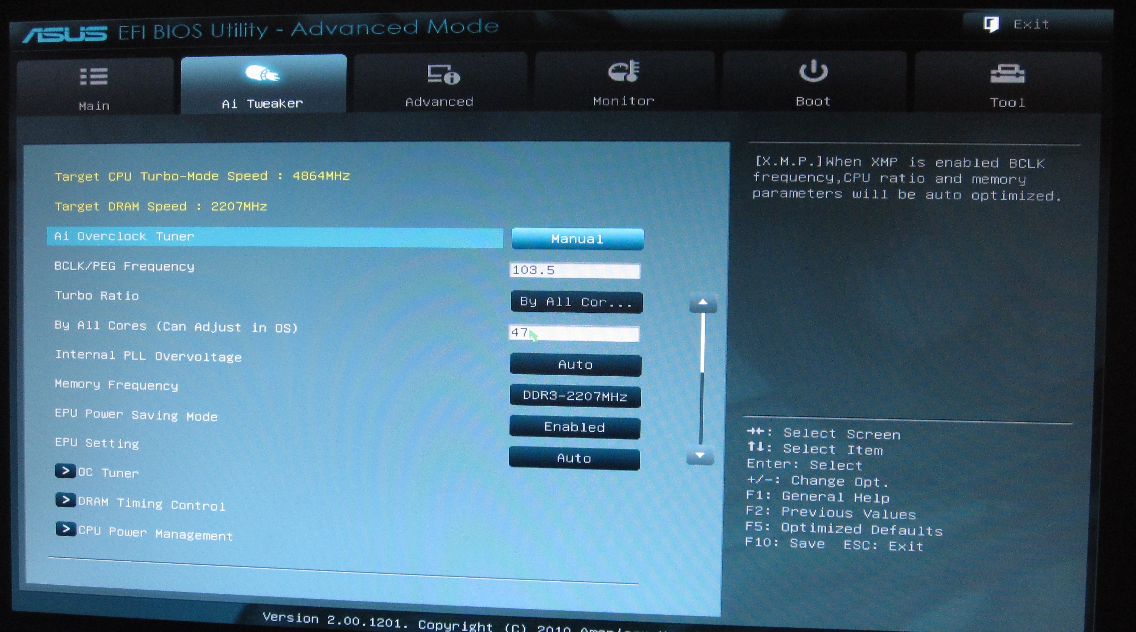
By clicking onto the advanced mode, we get a more BIOS-esque representation of all the motherboard features. The Ai tweaker provides all the overclocking tools we would expect, and more than you find in the Ai Suite in the OS. Features use either a text box for typing values, or a selection box for preset values. The user can utilise the mouse or the keyboard for either task.
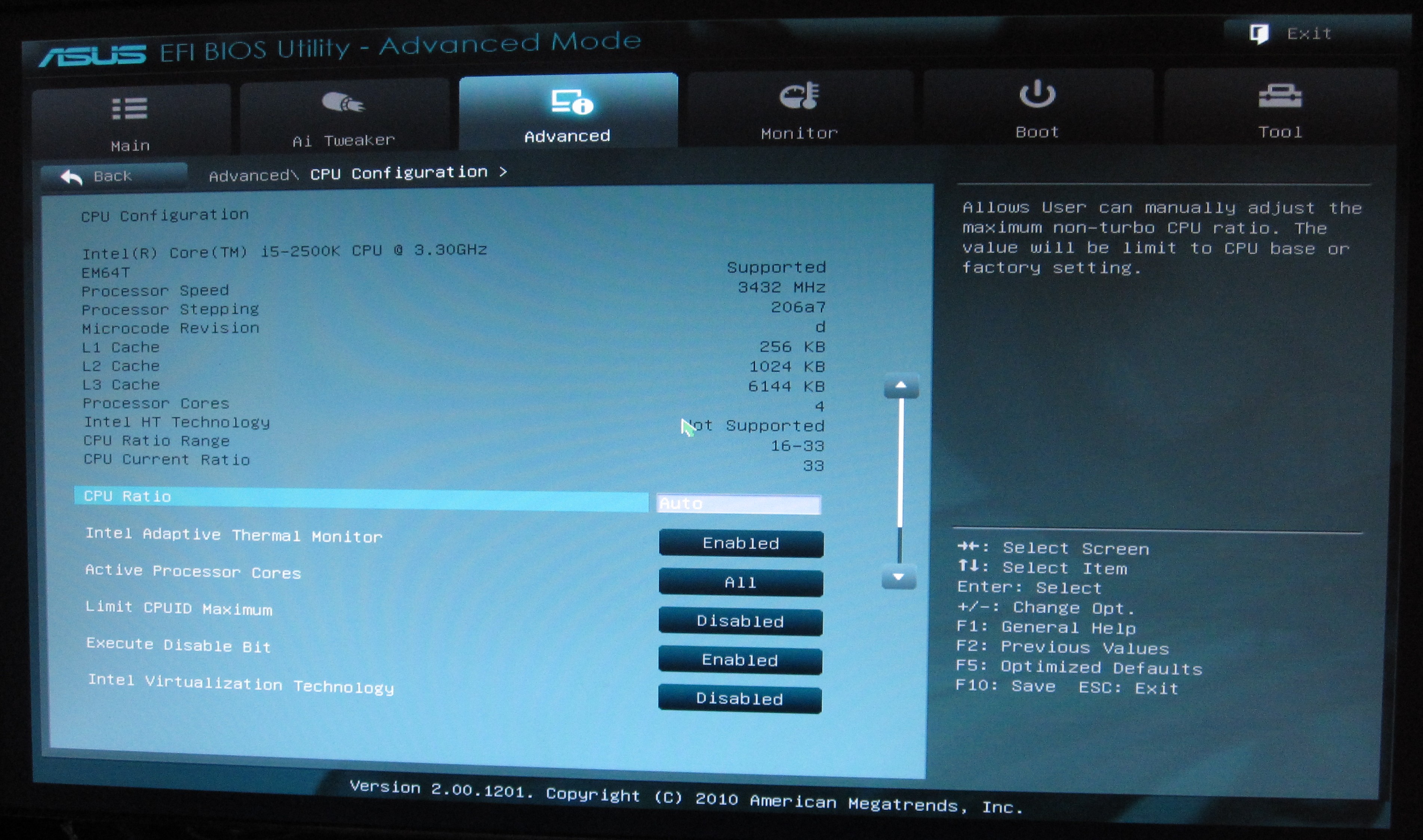
Elements such as enhanced sleep states appear under the Advanced CPU Configuration menu, where cores and ratios can be determined. In the Onboard Devices section, if you are not using the Marvell SATA ports, it is advised that this be switched off, to increase boot time by 1-2 seconds.
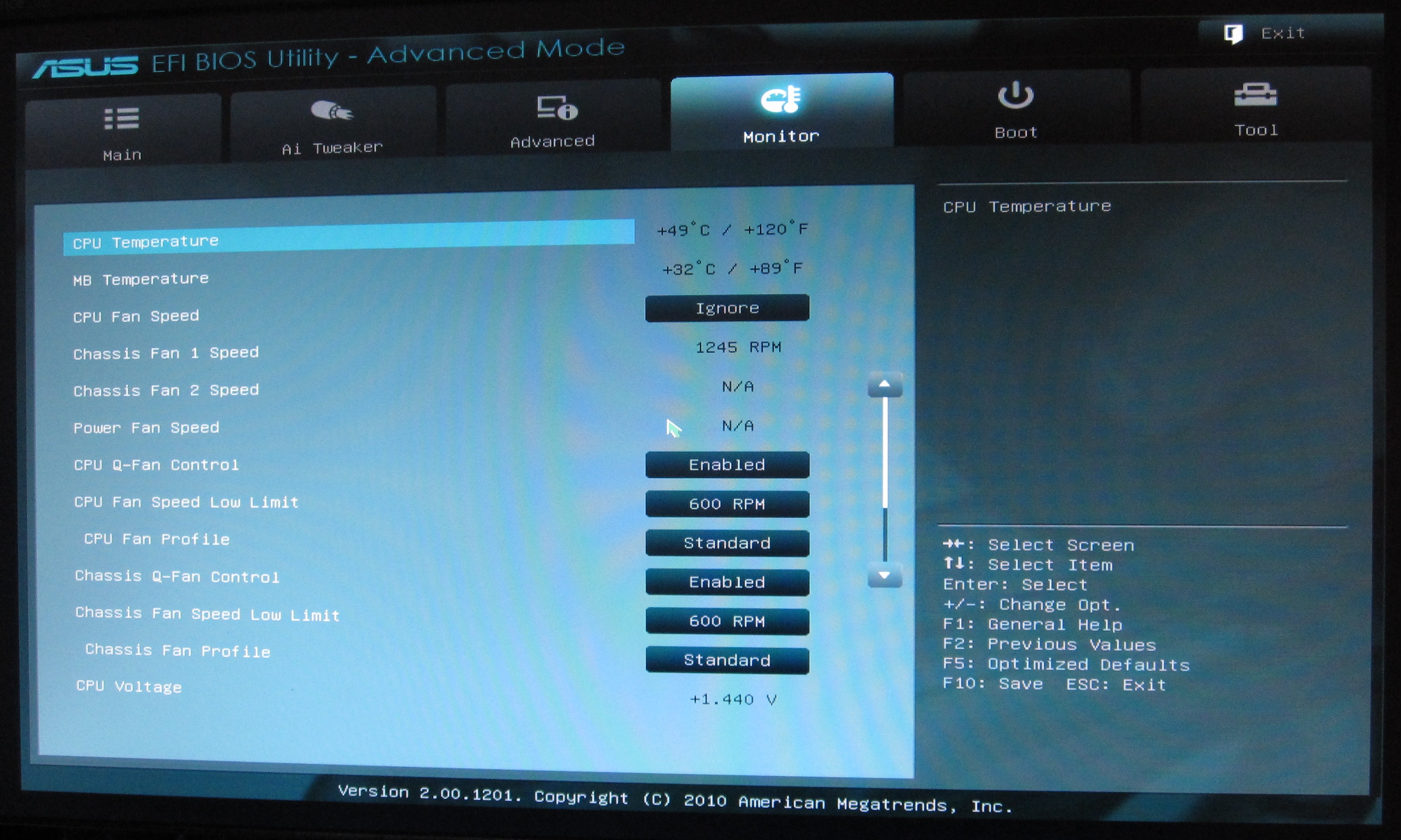
Fan controls are found in the Monitor tab, where a low limit fan RPM can be given and fan control can be switched between standard/silent/turbo/manual. In manual mode, you can adjust the upper and lower temperature of the fan and at which percentage speed it should run at those temperatures.
Users can specify advanced mode to be shown as soon as the UEFI is selected, and ten UEFI profiles can be saved. The UEFI can also be updated through the Tools tab if the latest file is supplied on a USB drive and plugged in before the ‘update’ option is chosen.


Overclocking
Overclocking on the P8P67 Pro was easy. The UEFI EZ mode offers a performance mode option, which on selecting, enabled the XMP profile of the memory, applied a 103 BCLK, and set the turbo limit to 42x, giving a 4.33 GHz overclock.
As the Ai Suite offers the ‘Auto Tuning’ option, I selected this in the OS and let the program do its thing. After a couple of reboots, and a BSOD, the OS booted into a screen showing a 43x multiplier at 103.5 BCLK (4.45 GHz), and attempted a series of stability tests, slowing increasing the BCLK by 0.5 every 30 seconds. At 105.5 BCLK, a BSOD screen appeared and seemed to crash halfway through, requiring me to reset the system physically. On the next boot, it was stated that the 43x103.5 overclock was applied and now usable. This system is likeable as it promises to adjust depending on how overclockable the processor is.
The downside is that the Ai Suite is quite conservative. I kept with the 103.5 BCLK and went into the UEFI. In advanced mode, adjusting the turbo ratio by one each time and rebooting led to a 46x multiplier (4.76 GHz) successfully passing stability tests. For 47x multiplier (4.86 GHz), I increased the PLL to 1.9V, CPU VCore to 1.42 V, and adjusted the short/long power limits to 150 W/130 W to get a successful stability test pass. This automatically set the memory to a command rate of 3T, so was set back to 1T manually. The 48x multiplier did not boot at this level, and I was not prepared to up the VCore or power limits any more. A 4.86 GHz overclock is very respectable!
At 4.86 GHz (47% OC over 3.3 GHz/non turbo/multithreaded, 31% OC over 3.7 GHz/turbo/single-threaded), the 3D Movement benchmark was run. In single thread mode, a score of 148.92 was achieved, a 31% increase. In multi-threaded mode, a score of 477.60 was achieved, a 37% increase.
Gigabyte has five P67 motherboards up for the US Sandy Bridge release – the P67A-UD3, the P67A-UD3P, the P67A-UD4, the P67A-UD5 and the P67A-UD7. At least the naming scheme is as easy to follow as previous generations – the higher the last number, the more expensive the board and the more features on offer:
| P67A Series | |||||
| P67A-UD3 | P67A-UD3P | P67A-UD4 | P67A-UD5 | P67A-UD7 | |
| Price | $130 | $160 | $190 | $260 | $320 |
|
SATA 6 Gb/s SATA 3 Gb/s eSATA |
2 4 0 |
2 4 0 |
2 4 2 |
2 4 2 |
4 4 2 |
|
CrossFireX SLI |
Yes No |
Yes No |
Yes Yes |
Yes Yes |
Yes Yes |
|
USB 3.0 USB 2.0 |
2 12 |
4 14 |
4 14 |
8 10 |
10 8 |
| LAN | 1 | 1 | 1 | 1 | 2 |
| PCIe |
2 x16 (1 x16, 1 x4) |
2 x16 (1 x16, 1 x4) |
2 x16 (2 x8) |
3 x16 (2 x8, 1 x4) |
4 x16 (2 x16 or 4 x8) |
Visual Inspection
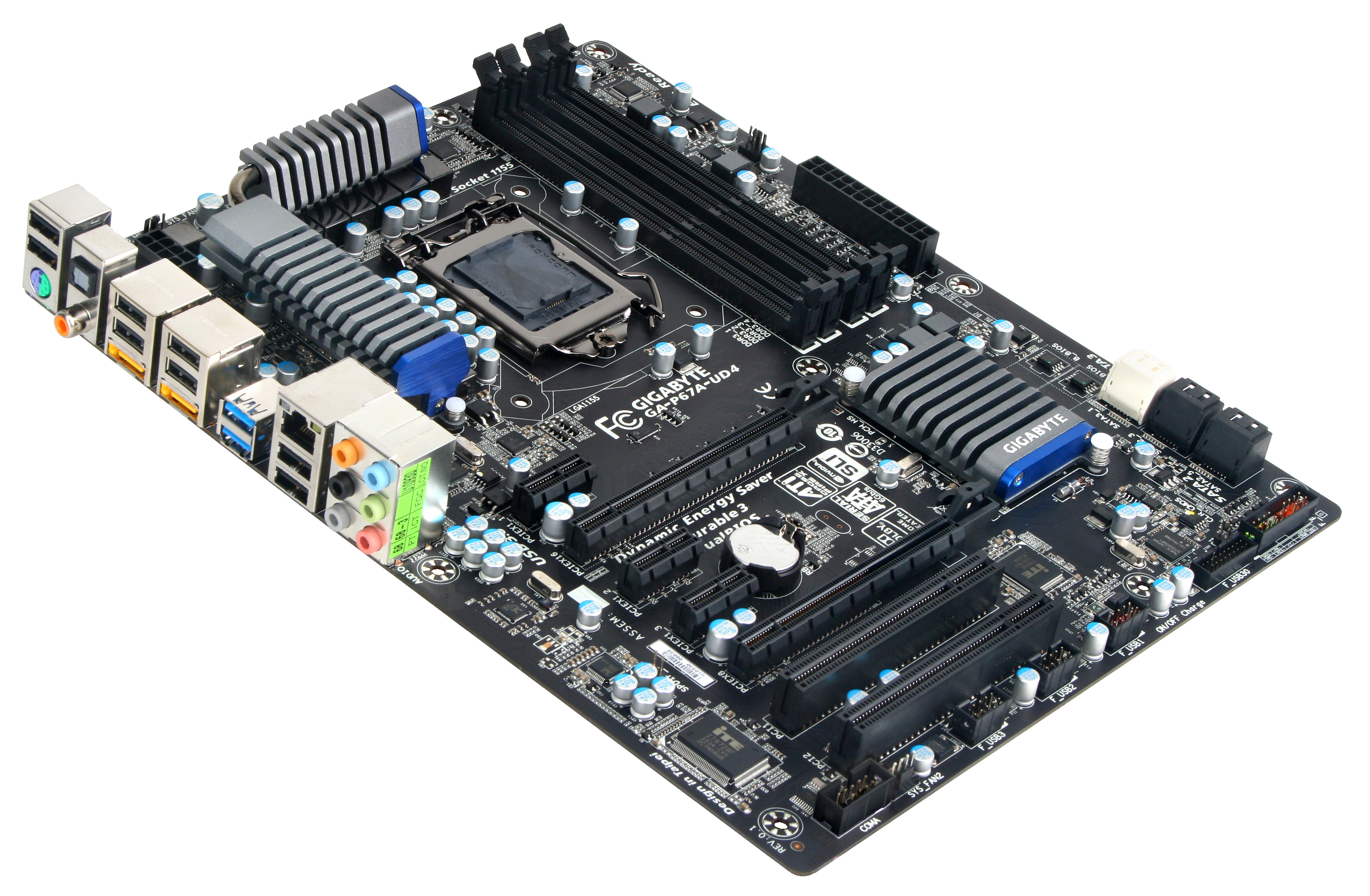
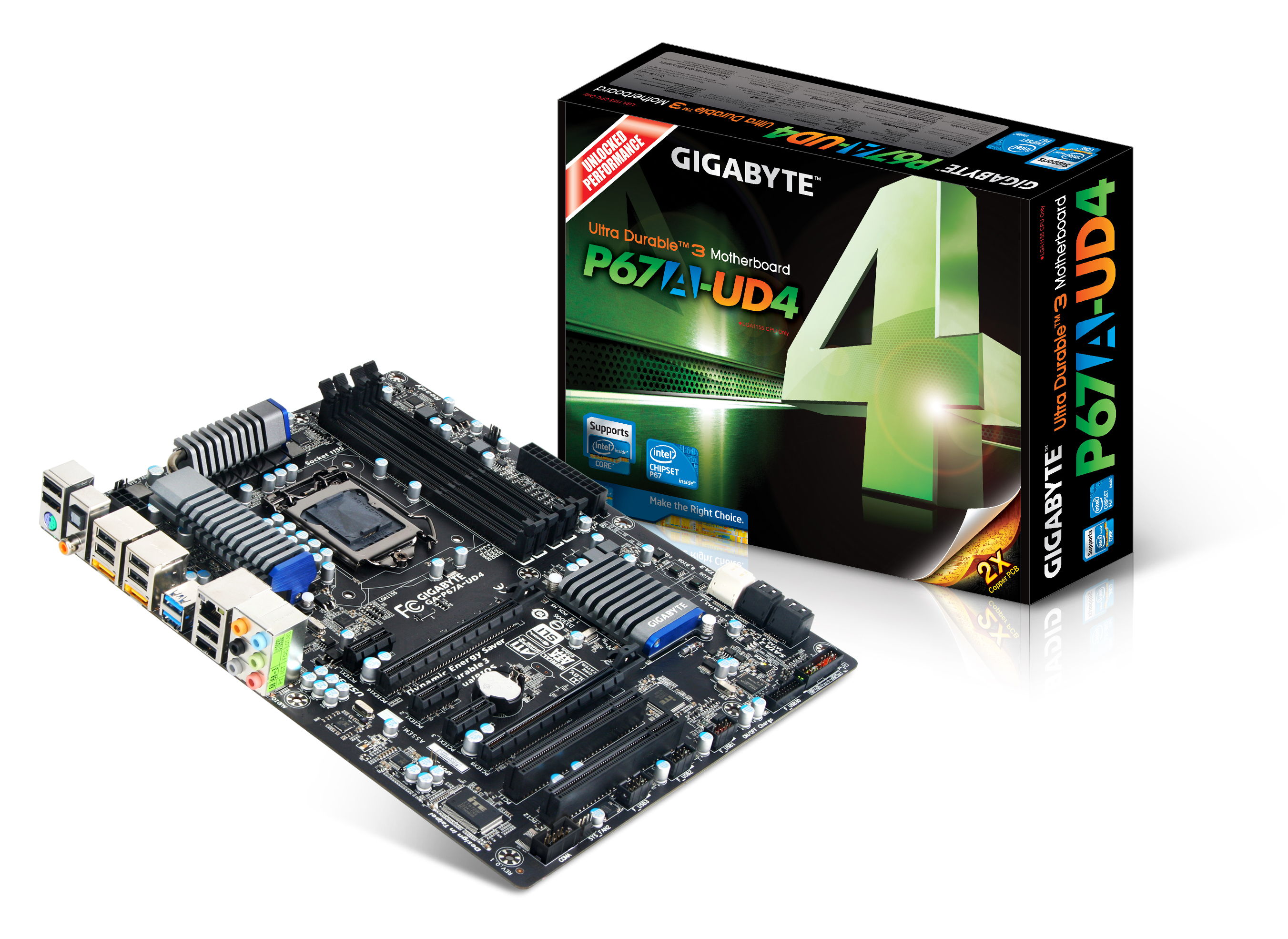
One of the first things I noticed about the P67A-UD4 was that it was not blue and white, like the majority of the Gigabyte motherboards have been recently that I have worked with. Predominantly featuring a black PCB, black PCIe connectors, black DIMM slots, black SATA 3Gb/s ports, a splash of white for SATA 6GB/s, silver chipset/FET coolers and a hint of old Gigabyte blue on those coolers is what we get this iteration. Not the whole range is like this – I have a H67 Gigabyte board on my desk here and that retains the blue and white credentials, as does the P67A-UD3.
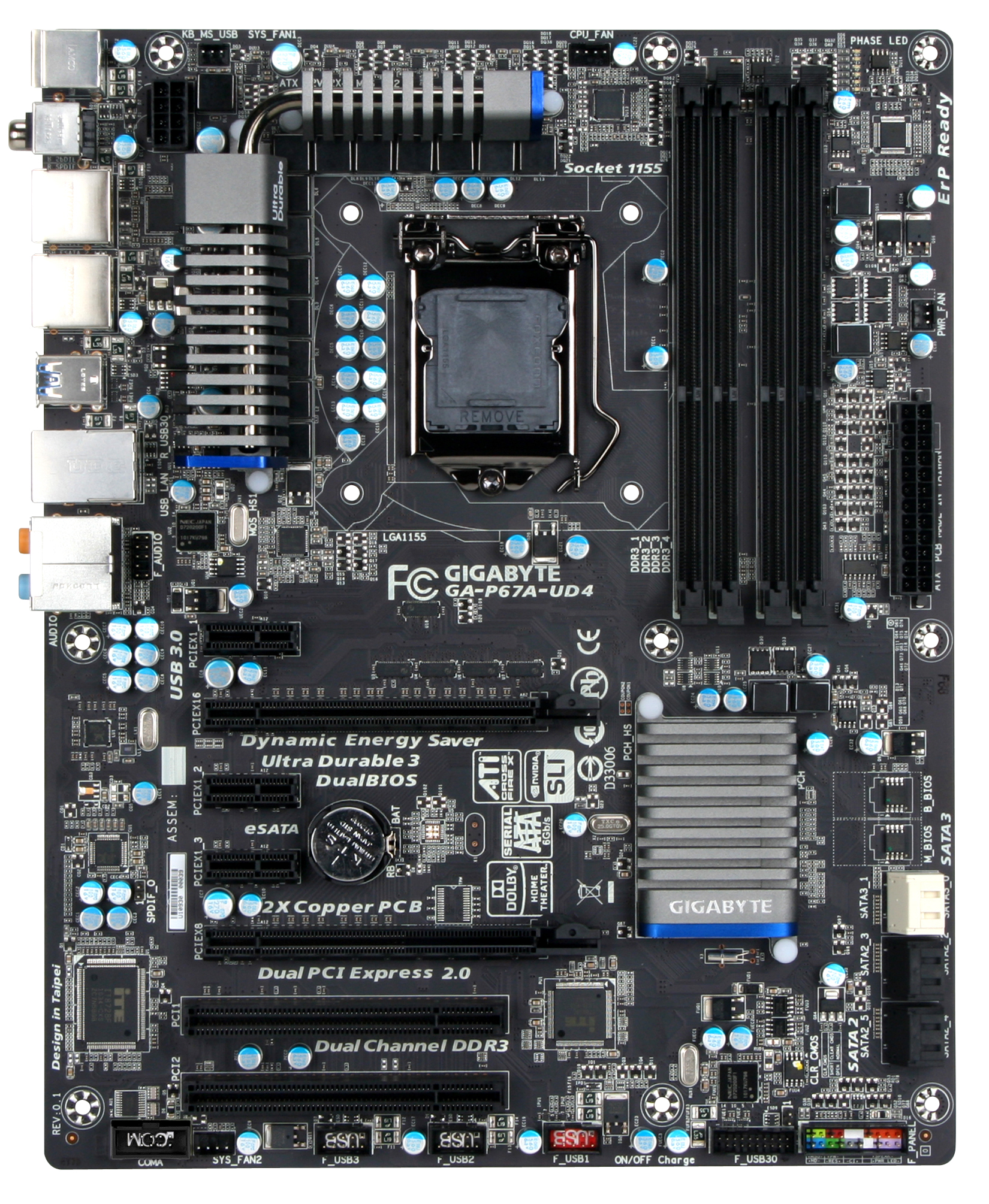
The PCIe layout is slightly different to other P67 boards I have reviewed – with only two PCIe x16 slots (going to x8/x8 in dual GPU mode), there is an extra PCIe x1 slot on the board. In a dual GPU setup, this leaves two PCIe x1 and a PCI slot still free on the board, as well as a gap between dual slot GPUs to aid in cooling.
Fan headers on the board are located near the 8-pin power connector, one above the socket, one above the 24-pin power connector, and one below the PCIe slots, which would only be covered if you have a dual slot PCI card.
Gigabyte’s dual BIOS system is on this board. Yes, that is right – BIOS. No UEFI here. Well, that's not strictly true, as one of the latest BIOS updates at the time of writing (F6) implements an EFI into the BIOS, reportedly allowing bootable access to hard drives over 2.2TB. This is due to, as Gigabyte explained, that their board is actually UEFI, but without a proper GUI interface like other boards. They've used the old BIOS-style interface for now, as after years of plugging away they believe it's quick, stable and recognisable for consumers to understand. So underneath, it's truly 64-bit, meaning 2.2TB+ partition support is possible, and could also suggest that a new GUI is coming in the future. I asked about time-scale for this, but Gigabyte were undoubtedly tight-lipped about dates and implementations.
Visually, in terms of the board, there is not much else to say – the space between the socket and the PCI slots is virtually clear. There are no power, reset or clear CMOS buttons on board, neither is there a debug LED, and which is a real shame given that ASRock can do it on a $150 motherboard. Compared to the ASUS board, all the energy saving and turbo performance options are all software based – no easy flick of switches here.
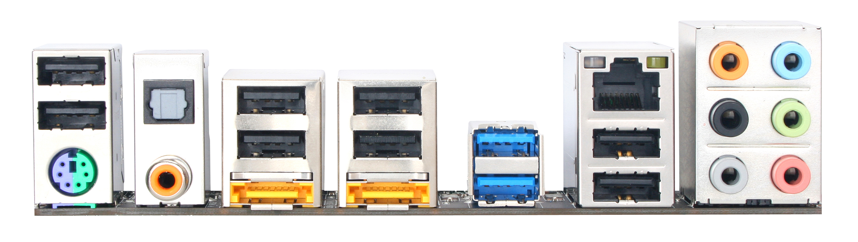
Like the other P67 boards, the back panel is regular as well. Only a single PS/2 connector, 8 USB 2.0 ports, 2 USB 3.0 ports, 2 eSATA ports, S/PDIF Out connectors, a single gigabit Ethernet, and audio I/O.
Board Features
| Gigabyte P67A-UD4 | |
| Market Segment | Performance |
| CPU Interface | LGA 1155 |
| CPU Support | i3/i5/i7 Sandy Bridge |
| Chipset | P67 |
| Base Clock Frequency | 80 MHz to 200 MHz in 0.1 MHz increments |
| DDR3 Memory Speed | 1333 MHz by default, 800-2133 MHz supported |
| Core Voltage | Auto, 0.750V to 1.700V in 0.005V intervals |
| CPU Clock Multiplier | Dependant on CPU |
| DRAM Voltage | Auto, 0.90V to 2.60V in 0.020V intervals |
| DRAM Command Rate | Auto, 1N to 3N |
| Memory Slots |
Four 240-pin DDR3 DIMM slots in dual-channel Regular unbuffered DD3 memory Up to 32GB total supported |
| Expansion Slots |
2 x PCI Express 2.0 x16 slots (PCIe 1 operates at x16 in single mode, PCIe 2 operates at x8 in single mode, or x8/x8 in dual) 3 x PCI Express 2.0 x1 slots 2 x PCI slots Supports ATI Crossfire Supports NVIDIA SLI |
| Onboard SATA/RAID |
a) 2 x SATA 6.0 Gb/s ports (white) supporting RAID 0, 1, 5 and 10 b) 4 x SATA 3.0 Gb/s ports (black) supporting RAID 0, 1, 5 and 10 c) 2 x eSATA 3.0 Gb/s ports from Marvell 88SE9128, RAID 0, 1 a) + b) are capable of cross channel RAID 0, 1, 5, 10 |
| Onboard |
4 x SATA 3 Gb/s w/ RAID 2 x SATA 6 Gb/s w/ RAID 2 x eSATA 6 Gb/s w/ RAID 1 x Front panel audio header 1 x S/PDIF Out header 3 x USB 2.0/1.1 headers 1 x USB 3.0/2.0 header via Renesas (NEC) D720200 chip 1 x Serial port header 1 x Clearing CMOS jumper |
| Onboard LAN | Gigabit Ethernet via Realtek RTL8111E |
| Onboard Audio | 7.1 channel Realtek ALC892 codec |
| Power Connectors |
24-pin EATX Power connector 8-pin EATX 12V Power connector |
| Fan Headers |
1 x CPU fan header 2 x System fan headers 1 x Power fan header |
| I/O Panel |
1 x PS/2 keyboard/mouse port 1 x Coaxial S/PDIF Out connector 1 x Optical S/PDIF Out connector 8 x USB 2.0/1.1 ports 2 x USB 3.0/2.0 ports via Renesas (NEC) D720200 chip 2 x eSATA 6Gb/s ports 1 x RJ-45 port 8-channel Audio I/O ports |
| BIOS Revision | F7 Beta |
In the Box
- I/O shield
- SLI 3-slot bridge
- 4 x right-angled SATA connectors
Compared to the ASUS P8P67 Pro, both boxes do not come with much in the way of extra peripherals. Here we get an SLI 3-slot bridge (compared to the 2-slot on the ASUS) but lose the USB 3.0 rear bracket, meaning that one will have to be obtained in order to use the USB 3.0 header on the Gigabyte board.
Software
Smart 6
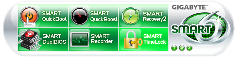
Smart 6 tries to encapsulate a good portion of the myriad of software available in easy-to-use quick buttons, and is essentially identical to the X58 and P55 iterations of the software. The QuickBoot portion attempts to speed up boot times by bypassing the lengthy BIOS post, assuming there has been no physical hardware change. QuickBoost is a single screen overclocking utility, similar to the EasyTune6 front page. Recovery2 helps roll back the system to a previous set of settings without predefinition of a backup time flag, and also the TimeLock, which is almost superfluous given Windows7 has Parental Controls.
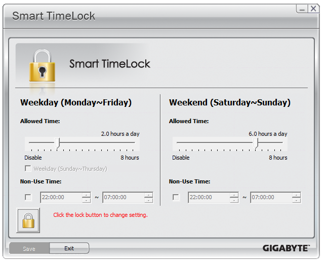
The idea behind TimeLock is similar to that on the Xbox360 parental controls – specify a certain number of hours per day (in this case, two different values for weekdays and weekends) for which the computer can be in use.
@BIOS
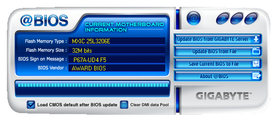
@BIOS is the staple Gigabyte BIOS update utility, and has been for a few iterations now. Users should note that to flash the latest BIOS files, the version of @BIOS on the CD is insufficient, and @BIOS 2.1 is required. 2.1 can be downloaded from the Gigabyte website.
Dynamic Energy Saver 2
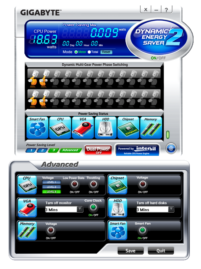
Another program that Gigabyte has been using on various chipsets is the Dynamic Energy Saver 2. As you can see from the picture, various power saving features can be enabled or disabled through user settings, or you can let the software determine the best course of action.
EasyTune6
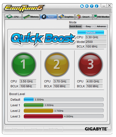
The OS overclocking tools are predominantly housed in EasyTune6. The front screen has those easy to use OC buttons, but only having three up to 4 GHz is somewhat limiting on the Sandy Bridge platform, given that most processors will happily do 4.4 GHz plus. There is no system of auto-overclocking detection similar to the ASUS boards.
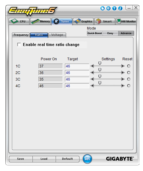
Despite the software having an option for ‘real time ratio change’, of which there is an option in the BIOS to enable/disable, I could not get this to work. Upon setting a new multiplier, I was asked to reboot to apply it.
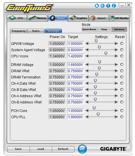
As always with EasyTune6, going to advance mode allows voltage manipulation. While it is nice to have such a wide variety of options, given that for Sandy Bridge all you really need is CPU VCore, DRAM and CPU PLL, it would have been easy just to include those in the ‘easy’ mode.
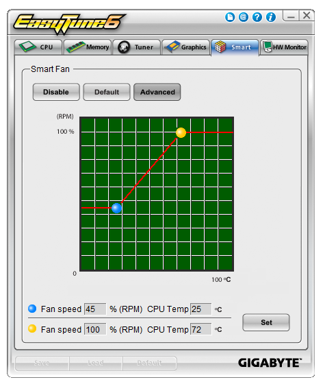
Fan control is basic in EasyTune6. Even in advanced mode, as shown above, you can choose where to put the initial and final ramp positions in terms of temperature against max RPM, but there is no option to define further points on the curve, or no determination of separate fans, so all chassis fans will be controlled by this one profile.
BIOS
Gigabyte has not been on the ball BIOS/UEFI wise for Sandy Bridge. In the Visual Inspection, I explained at how the board is actually 64-bit UEFI but with a BIOS interface attached (for stability, after years of working at it) with plans to possibly upgrade to a GUI at a later date. Though in the name of stability, the launch BIOS has significant issues with turbo boosting, where only a 1x multiplier boost gets applied at any thread loading, rather than 4x/3x/2x. It wasn't as simple as downloading the latest BIOS from the website and updating - in order to get it to work properly, I had to load in an OS, and download the latest version of @BIOS, their BIOS updating tool, and grab the latest BIOS. You cannot use the version of @BIOS on the CD, you need the latest version, and you cannot use QFlash in the BIOS, as they both do not recognise any BIOS F6 or above as valid. I downloaded the latest BIOS file from the website, and use @BIOS to update from the file. At the time of writing, the F7b BIOS is the latest, which implements turbo modes correctly.

If you have worked with a BIOS before, Gigabyte is not throwing up too many new features to surprise you – only those based around Sandy Bridge. Everything overclocking, CPU and voltage related is found in the Intelligent Tweaker menu, whereas boot order can be found in the advanced BIOS options.
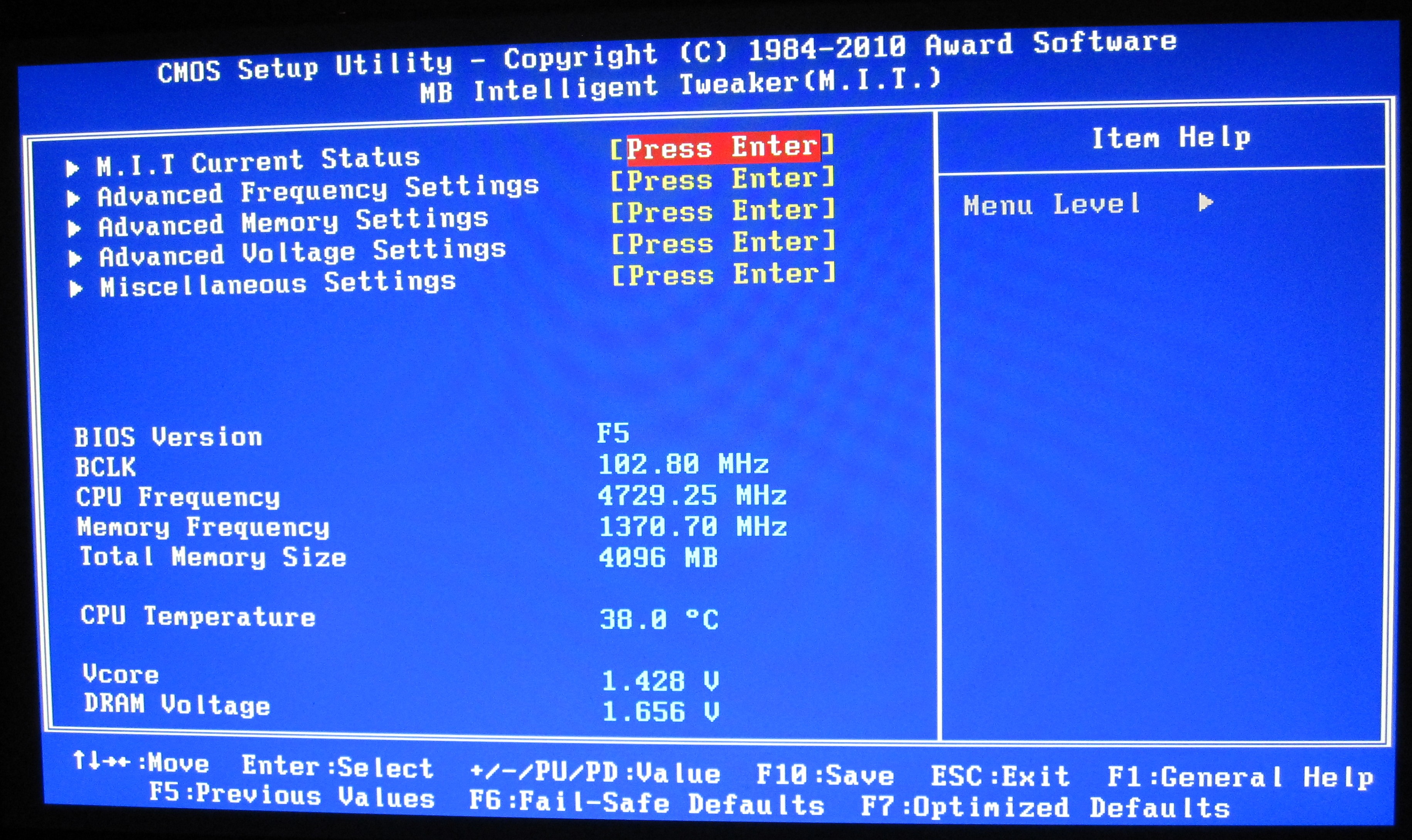
The Intelligent Tweaker menu gives a quick overview of BCLK, frequency, temperature, voltages, etc. By dividing the all the OC options into the ‘frequency’, ‘memory’, and ‘voltage’ sub-menus, while this splits up the options to make them easier to digest, it does result in more navigation. Personally, I would prefer being able to adjust the CPU/DRAM voltages in the frequency settings as well as the voltage settings.
Thankfully, most of the settings can be adjusted by typing in a value, or by the +/- buttons, or by pressing enter to type/bring a scrollable menu up. I like being able to do this in a BIOS/UEFI, and most manufacturers will leave out at least one of the available ways to change a setting in every sub-menu, or mix and match as they deem appropriate.
The BIOS allows eight profiles to be saved on board, or you can save/load to a file. Given some of the overclocking problems I mention below, every time a re-flash of the BIOS was required, all my saved on board settings were lost.


Overclocking
Overclocking on the P67-UD4 was almost as easy as it has been on previous BIOS boards, although there was no easy overclock presets available in the BIOS. EasyTune6, the OS software on the Gigabyte CD, gives automatic options for 35x, 37x and 40x multiplier at 100 MHz bus speed. These settings, as in previous Gigabyte iterations and boards, work pretty well, but a 4 GHz overclock on Sandy Bridge is not going to win any awards.
Going into the BIOS, I immediately left everything on auto and upped the multiplier to 45x, for a 4.5 GHz processor speed. This successfully booted into Windows, passed the stability tests, then BSOD on shutdown. On the restart, the board attempted to boot back at stock, which was disappointing.
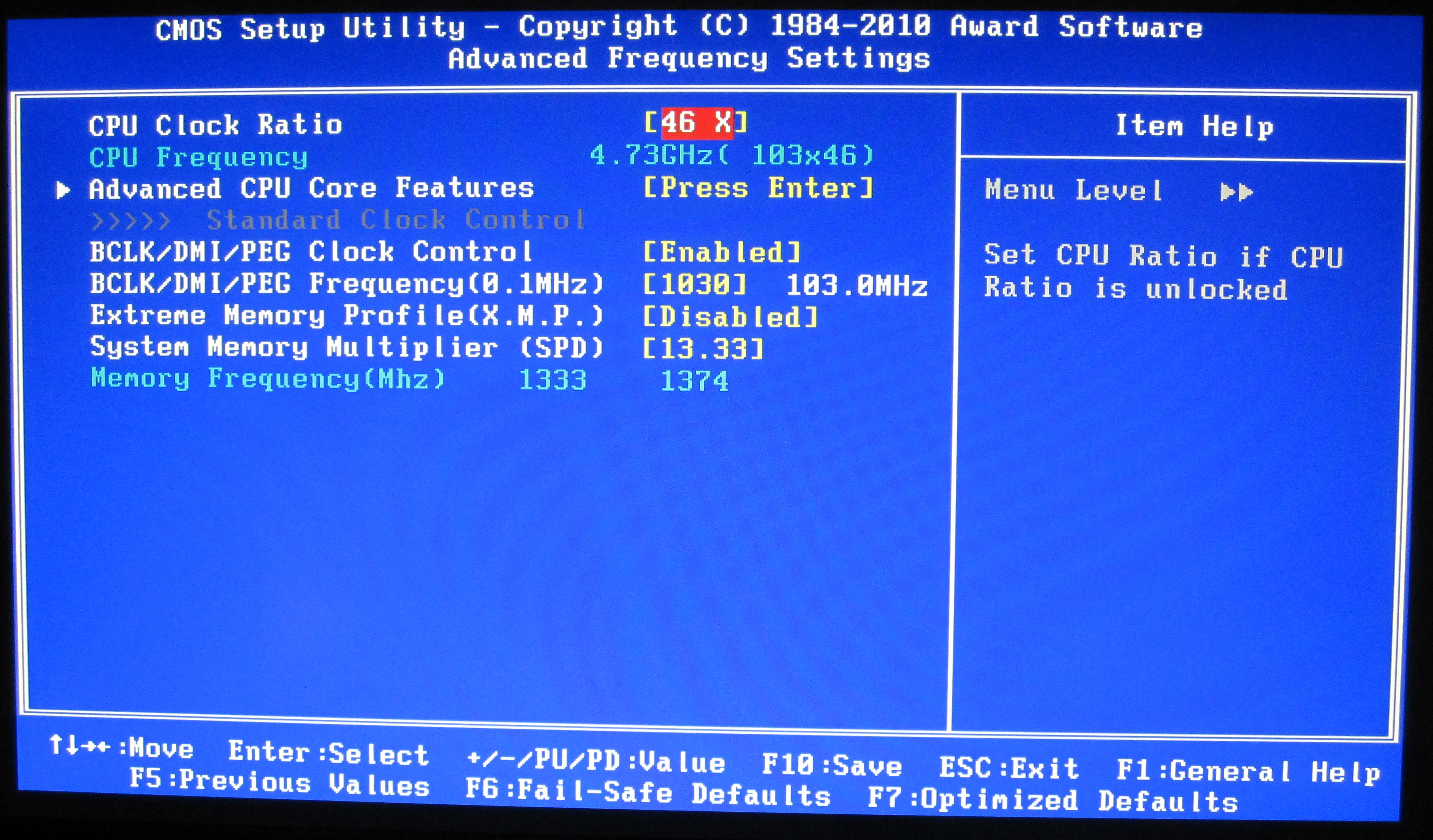
As with previous overclocking attempts, I jumped in and put the VCore straight at 1.42V, with a 1.9V PLL. Upping the multiplier to 45x to give 4.5 GHz this time was no trouble. 4.6 GHz and 4.7 GHz also passed without issue. 4.8 GHz booted into the OS, but failed the OCCT stress test, so I rolled back the multiplier to 47x and started playing with the BCLK by 1 MHz at a time. 101 MHz also failed the stress test, leaving 47 * 100 MHz as a good overclock. This board automatically puts a -0.2 MHz bias on the BCLK, meaning that the speed is actually 47 * 99.8 MHz = 4.69 GHz.
Out of interest, I rolled back the multiplier again to 46x and upped the BCLK this way. With a 102.2 MHz BCLK, it would beat the speed of the 47 * 100 MHz overclock, so I booted at 102.5 MHz (102.3 MHz effective), with a 46x multiplier, which passed. 103 MHz did not however, so 102.5 MHz * 46 (102.3 MHz * 46 effective = 4706 MHz) would seem the best option, as it contains that small little BCLK boost to help other components and memory.
With the board’s Dual BIOS system, on a severe failed boot type unsuccessful overclock by increasing the multiplier too much, the board would revert to the backup BIOS, and then boot me straight into the BIOS. If I changed anything, it would load the standard BIOS again with my new settings. Also of note, if I upped the BCLK too far, the system would restart in one of two ways – without any overclock at all, or at 100 MHz with my chosen multiplier. If I increased the RAM too far, it would keep rebooting and never getting to the POST screen until I used a jumper on the Clear CMOS header. Note, no jumpers are included in the box, so you have to find your own way of shorting those pins. I also tried going for 50x multiplier, 100 MHz BCLK, at 1.50 V. On a failed boot into Windows, the main BIOS became corrupted and had to be restored by the backup – then I had to load into the OS to run @BIOS to update to the F7b BIOS again, because the backup BIOS is F1 and doesn’t recognise the F7b BIOS file as a valid BIOS, which was frustrating.
At 4.706 GHz (42.6% OC over 3.3 GHz/non turbo/multithreaded, 27% OC over 3.7 GHz/turbo/single-threaded), the 3D Movement benchmark was run. In single thread mode, a score of 145.19 was achieved, a 28% increase. In multi-threaded mode, a score of 463.12 was achieved, a 38.6% increase.
| Test Setup | |
| Processor |
Intel i5-2500K ES – 3.3 GHz (3.7 GHz Turbo) 4 Cores, 4 Threads, 6MB L3 |
| Motherboards |
ASUS P8P67 Pro Gigabyte P67A-UD4 |
| Cooling | Corsair H50-1 Water Cooler |
| Power Supply | Enermax Modu87+ 600W 80PLUS |
| Memory |
Patriot Viper Xtreme DDR3-2000 9-10-9-27 2x4GB Kit, 1.65V Patriot Viper Xtreme DDR3-2133 9-11-9-27 2x2GB Kit, 1.65V Corsair Vengeance DDR3-1600 9-9-9-24 2x4GB Kit, 1.50V |
| Memory Settings | Patriot Viper Xtreme DDR3-1333 9-9-9-24 2x2GB |
| Video Cards | XFX HD 5850 1GB |
| Video Drivers | Catalyst 10.12 |
| Hard Drive | Intel X25-M 80GB SSD Gen2 |
| Optical Drives | LG GH22NS50 |
| Case | Open Test Bed – CoolerMaster Lab V1.0 |
| Operating System | Windows 7 64-bit |
| USB 2/3 Testing | Patriot 64GB SuperSonic USB 3.0 |
Power Consumption and CPU Temperature
Power consumption was tested on the default system as a whole with a wall meter connected to the power supply, using a dual GPU configuration. This method allows us to compare the power management of the UEFI/BIOS and the board to supply components with power under load, and includes typical PSU losses due to efficiency. These are the real world values that consumers may expect from a typical system (minus the monitor) using these motherboards.
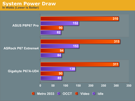
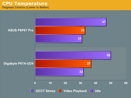
Neither system does too badly in power consumption readings, but the Gigabyte is behind on temperature deltas. This could easily be attributed to the mounting - while every attempt is made to repeat the mounting technique, there is always a range of statistical variation, so the 2-4ºC difference is nothing obvious to be concerned about.
USB Speed
For this benchmark, we run CrystalDiskMark to determine the ideal sequential read and write speeds for the USB port using our 64GB Patriot SuperSpeed USB 3.0 drive. Then we transfer a set size of files from the SSD to the USB drive, and monitor the time taken to transfer. The files transferred are a 1.52 GB set of 2867 files across 320 folders – 95% of these files are small typical website files, and the rest (90% of the size) are the videos used in the Sorenson Squeeze test.
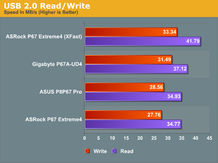
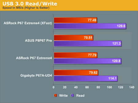
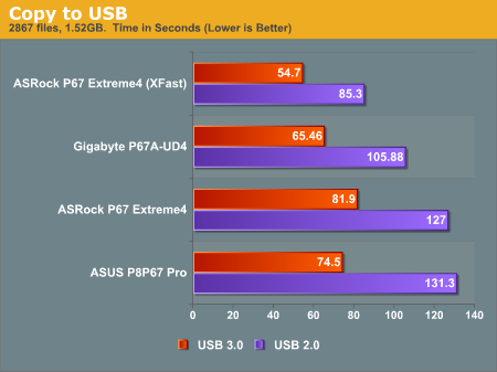
The Gigabyte board overall has the better USB performance, especially in USB 3.0 read speeds. This is accurately translated by the difference in copy time difference between the ASUS and Gigabyte boards in both USB 2.0 and USB 3.0.
3D Movement Algorithm Test
The first benchmark ran is actually one I have written. My full time job involves computational chemistry, so this first benchmark uses various algorithms for three-dimensional simulation and movement of independent particles. The algorithms both employ uniform random number generation or normal distribution random number generation, and vary in various amounts of trigonometric operations, conditional statements, generation and rejection, fused operations, etc. The benchmark runs through six algorithms for a specified number of particles and steps, and calculates the speed of each algorithm, then sums them all for a final score. This is an example of a real world situation that a computational scientist may find themselves in, rather than a pure synthetic benchmark. The benchmark is also parallel between particles simulated, and we test the single thread performance as well as the multi-threaded performance.
There's barely anything between the boards. The Core i7-920 pulls ahead at stock as it has 8 threads to tackle the workload, whereas the i5-2500K used in the P67 motherboards only has four.
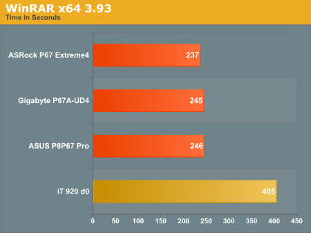
WinRAR x64 3.93
With 64-bit WinRAR, we compress the set of files used in the USB speed tests. WinRAR x64 3.93 attempts to use multithreading when possible.
FastStone Image Viewer 4.2
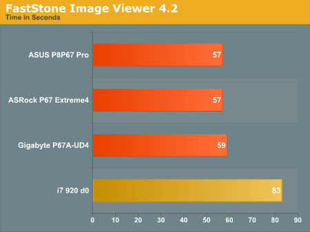
FastStone Image Viewer is a free piece of software I have been using for quite a few years now. It allows quick viewing of flat images, as well as resizing, changing color depth, adding simple text or simple filters. It also has a bulk image conversion tool, which we use here. The software currently operates only in single-thread mode, which should change in later versions of the software. For this test, we convert a series of 170 files, of various resolutions, dimensions and types (of a total size of 163MB), all to the .gif format of 640x480 dimensions.
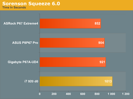
Sorenson Squeeze 6.0
Sorenson Squeeze is a professional video encoder, complete with a vast array of options. For this test, we convert 32 HD videos, each a minute long and approximately 42 MB in size, to WMV 512KBps format. Squeeze can encode multiple videos at once, one for each thread.
Conclusions
There is not much in it, but the ASUS board performs better in most benchmarks with one exception - the USB speed (especially the USB 3.0 read) is a step behind the Gigabyte.
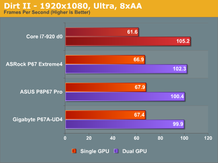
Dirt 2
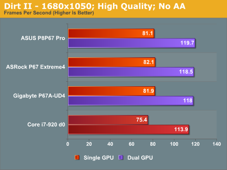
Dirt 2 came to the PC in December 2009, developed by Codemasters with the EGO Engine. Resulting in favourable reviews, we use Dirt 2’s inbuilt benchmark under DirectX 11 to test the hardware. We test two different resolutions at two different quality settings, in single and dual GPU setups.
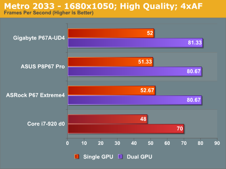
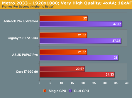
Metro 2033
Metro 2033 is the Crysis of the DirectX 11 world (or at least until Crysis 2 is released), challenging every system that tries to run it at any high-end settings. Developed by 4A Games and released in March 2010, we use the inbuilt DirectX 11 benchmark to test the hardware.
Conclusions
You cannot really budge any of the boards in their 3D performance. The Gigabyte board technically performs worse than either of the other P67 boards benchmarked, but the differences between them could easily be masked by statistical variance.
Final Words
Both the ASUS P8P67 Pro and Gigabyte P67A-UD4 motherboards offer a lot to consumers. For $190, we want a product that hits all the basic functionality of Sandy Bridge, and squeezes out as features and as much performance as possible at this price point.
For the ASUS board, we have a nice looking product with significant strengths in the implementation of their UEFI, and the auto overclockable functions available. The UEFI EZ mode/basic starting screen is something many manufacturers will copy over the upcoming months and UEFI visions. The auto-tuner section of Ai Suite will see use in all markets, aiding various retailers in offering ready-overclocked Sandy Bridge bundles with the P8P67 Pro. Intel gigabit Ethernet is nothing to be sniffed at, and the fan controls can only help improve the user experience. Also, bundle in that three-year warranty. On the downside, the BT GO! and Turbo Remote overclocking features via Bluetooth did not work for me.
The Gigabyte board performs on par with the ASUS board in terms of benchmarking – in most situations, there is almost nothing in it (except USB, where Gigabyte have the advantage there). The board is UEFI GUI absent (for now, supposedly), but thanks to BIOS updates, now supports 2.2TB+ hard drives. Overclocking via the BIOS is straightforward if you have ever overclocked before, and the myriad of software available in the OS will keep you hunting for options, trying to remember which setting is in which piece of software. The warranty, like the ASUS, is also three years. However, the BIOS updating issues I had are certainly worthy of note.
After playing with both boards, I can only come to one conclusion – if it were my money, I would take the ASUS P8P67 Pro over the Gigabyte P67A-UD4. With the ASUS board, you are getting a detailed UEFI, an awesome auto-overclocking tool, better energy saving features, a USB 3.0 bracket , more SATA 6 Gb/s ports, Intel gigabit Ethernet, and in my case, scope for a better overclock. The Gigabyte board is essentially expensive for what is on offer, in terms of usability, features, and extras.
However, the second question is: ‘what about the comparison to the ASRock P67 Extreme4’? The ASRock board has power/reset buttons on the board, a Debug LED, that USB 3.0 bracket which will hold an SSD (worth in my option about $15), and is almost $40 cheaper. The ASUS board is the slightly better performing, overclocking is easier on the ASUS, the ASUS has a longer warranty, the UEFI is slightly better on the ASUS, the ASUS uses Intel Ethernet rather than Realtek, but the ASRock will take socket 775 coolers. It is up to you to judge, but in my opinion, I would take the Extreme4, pocket the $40 difference, and invest it in something else for a PC build.
This then leads into the following question – ‘if I’d rather take a $150 board rather than a $190 board, why are there $300 boards available?’ That question is to be tackled over the coming months!


